
Power
Arc Ignitions
Precision
Performance for
1, 2, 3, 4, 6 & 8 Cylinder
Engines
|
|
| |
Power
Arc Ignitions
Precision
Performance for
1, 2, 3, 4, 6 & 8 Cylinder
Engines
|
TROUBLE SHOOTING GUIDE
Before proceeding verify the following: ● Resistor plugs and resistor plug
wires or Power Arc approved high resistance spiral wires are being
used.
● The ignition has been correctly
wired and timed. If you have sensor wires make sure the
proper wires are grounded to select the correct ignition map or
curve. Please refer to your owners
manual for timing procedures and wiring diagrams.
If you cannot determine the problem after going through the troubleshooting guide below you may click here to ask Power Arc a question. If you wish to have an ignition component tested click here. If troubleshooting the ECP (Edge Card Programmer) click here. WARNING: If using a battery charger never attempt to start the engine or apply power to the ignition with the charger attached. Remove charger before starting. If the engine utilizes a starter motor and will not turn over after charging replace the battery or repair starter motor, cables etc. Disconnect battery positive cable before charging if a defective battery is suspected. |
|
Problem: Engine turns over but will
not start.
● Poor connections in ignition
power circuit (connectors, breaker, ignition switch & kill
switches). Perform the voltage test or
perform the quick wiring test.
● Defective encoder disk teeth
missing or bent. Inspect encoder disk. Make sure the
encoder disk is centered or slightly below center in optical
triggers. If the encoder disk is rubbing against the case of the
optical sensor it can damage the apertures. Click here
for alignment instructions.
● Blocked optical sensor.
Static timing light stuck on or off when engine is turned over.
The static timing light should blink on at TDC. Clean the
apertures of optical sensor. Click here for
cleaning instructions.
● Incorrect ignition timing.
Please refer to your owners manual
for timing procedures.
● Defective coil wiring.
Perform the voltage test.
● Defective coil, spark plug or
ignition wires. Perform high voltage test.
● Fuel system problems.
Check for fuel in the cylinder.
|
Problem: Engine dies when going over
a bump.
● Poor connections in ignition
circuit (connectors, breaker, ignition switch & kill
switches). Perform the voltage test
or perform the quick wiring test. Run
your hands along the wires to find melted or bare wires.
Visually inspect all wires looking for melted or crimped
wires. Tug on wires with moderate pressure at connectors,
fuses or switches to verify they are securely attached.
|
Problem:
Engine dies or when running appears to have a low Rev. limit
● Poor connections in ignition
circuit (breaker, ignition switch & kill switches). Perform
the voltage test or perform the quick wiring
test. Check heat shrunk connections closely (wires break
at connector crimp/solder joint). Intermittent connections
often cause this problem. Visually inspect all wires looking for
melted or crimped wires. Run your hands along the wires to
find melted or bare wires. Tug on wires with moderate
pressure at connectors, fuses or switches to verify they
are securely attached.
● Defective charging system.
Perform a charging system test.
● Make sure the encoder disk is centered or slightly below center in optical triggers. If the encoder disk is rubbing against the case of the optical sensor it can damage the apertures and cause erratic operation. Click here for alignment instructions. ● Improper gas cap venting. Remove cap check vent hole. |
Problem: Engine hesitates/stumbles
when starting from stop especially when hot
● Plug heat range wrong. Go
to a colder plug. The plug may be glowing red meaning the
fuel will pre-ignite in the cylinder.
|
Problem:
Engine misfires
● Bad spark plug or spark plug
wire. Perform high voltage test.
Install new spark plugs.
● Problem with carburetor. Carburetor too lean. ● Poor connections in ignition
circuit (breaker, ignition switch & kill switches). Perform
the voltage test or perform the quick
wiring test. Check heat shrunk connections closely
(wires break at connector crimp/solder joint).
Intermittent connections often cause this problem. Visually
inspect all wires looking for melted or crimped wires. Run
your hands along the wires to find melted or bare wires.
Tug on wires with moderate pressure at connectors, fuses
or switches to verify they are securely attached.
● Make sure the encoder disk is
centered or slightly below center in optical triggers. If the
encoder disk is rubbing against the case of the optical sensor
it can damage the apertures and cause erratic operation. Click here for alignment or refer to owner's manual.
|
Problem:
Spark plug wire popping off coil.
● Ignition coil wire spring too
long. Shorten spring. Click here
for proper lengths.
● Silicone grease or silicon spray
used. Clean off coil tower do not use silicone grease or
spray on the coil tower portion of the spark plug wire.
● Use cable tie on coil boot of
spark plug wire to secure boot to coil tower.
Problem: Only one cylinder will fire ● Bad coil, spark plug, or spark
plug wire. Perform high voltage test.
● No power to coil
leads. Perform the voltage test on the
coil.
● Module wire not connected to
coil trigger, wire broken internally or inside of
connector.
● Pinched, melted, broken or
shorted coil trigger wire. Visually inspect wires running to
coil.
Problem: Hard starting or engine starts when starter button released ● Weak or undersized
battery. Perform the voltage test.
● Poor connections in ignition
power circuit to coils or module (breaker, ign. & kill
switches). Perform the voltage test or
perform the quick wiring test.
● Incorrect timing. Recheck
static timing.
● Spark plug gap too large.
Measure plug gap and adjust. Click here for spark plug and
ignition wire tips.
Problem: Erratic operation, tachometer bounce ● Solid or low resistance spiral
core spark plug wires being used. Click here
for section on testing spark plug wires.
● Defective charging system.
Perform a charging system test.
● Intermittent connection in
wiring harness. Check heat shrunk connections closely
(wires break at connector crimp/solder joint). Visually
inspect all wires looking for melted or crimped wires. Run
your hands along the wires to find melted or bare wires.
Tug on wires with moderate pressure at connectors, fuses
or switches to verify they are securely attached.
● Make sure the encoder disk is
centered or slightly below center in optical triggers. If the
encoder disk is rubbing against the case of the optical sensor
it can damage the apertures and cause erratic operation.
Problem: Engine starts then suddenly shuts off engine briefly run when power to the ignition module is cycled and and engine restarted ● Blockage of optics. Clean
with alcohol and blow out with air. Make sure the encoder
disk is centered or slightly below center in optical triggers.
If the encoder disk is rubbing against the case of the optical
sensor it can damage the apertures. Click here
for cleaning and alignment instructions.
● Defective encoder disk teeth
missing or bent. Inspect encoder disk. Make sure the
encoder disk is centered or slightly below center in optical
triggers. Click here for cleaning and
alignment instructions.
Problem: Static timing LED stays locked on ● Blockage of optics. Clean
with alcohol and blow out with air. Make sure the encoder
disk is centered or slightly below center in optical triggers.
If the encoder disk is rubbing against the case of the optical
sensor it can damage the apertures. Click here
for cleaning and alignment instructions.
Problem: Poor acceleration. Black soot in pipes ● Fuel octane too high.
● Incorrect sensor map.
Recheck sensor wires. Map is too retarded.
● Carburetor problem.
Carburetor too rich.
Problem: Poor acceleration/hesitation pinging/popping. ● Carburetor problem.
Carburetor too lean.
Problem: Popping and rattling in exhaust pipes when decelerating ● Fuel octane too high.
● Timing too far retarded.
Incorrect sensor map recheck sensor wires.
Problem: Kicks back when starting ● Timing too advanced. Refer
to owner's manual and recheck static timing.
● Voltage drop to ignition when
starter motor is engaged. Perform the voltage
test.
Problem: Ignition will not retard under heavy load or acceleration ● VOES wire or sensor wire on
ignition module not grounded.
● Defective VOES or vacuum switch.
● Shorted or broken sensor wire.
Problem: Tail pipes blue, hollow sound in pipes, runs sluggish ● Ignition static timing too far
retarded. Recheck static timing or change timing map.
● VOES or vacuum switch not
operating or activating at wrong vacuum.
● Bad connection from wire to VOES
or vacuum switch.
Problem: Spark present at plugs with engine backfiring or wont start ● Incorrect timing. Recheck
Static timing.
● Weak spark due to low
voltage. Perform the voltage test.
● Make sure plug wire is attached
to the correct coil. Refer to owner's
manual.
● Make sure ignition module output
wires are attached to the correct coil.
● Fuel system problem.
Problem: Pinging when leaving the line ● Timing to far advanced.
Recheck static timing or change timing map wrong sensor wires
may be grounded (connected to -12 VDC).
● Accelerator pump or enrichener
not set correctly or not operating.
● Fuel vent cap not working.
Problem: Pinging in the mid-range ● Timing too far advanced.
Recheck static timing or change timing map. Wrong sensor
wires may be grounded/ungrounded (connected to -12 VDC).
● VOES or vacuum switch not
operating or activating at wrong vacuum.
● Bad connection from wire to VOES
or vacuum switch.
● Carburetor too lean.
Voltage Test ● Set volt meter to 20 Volt DC or
higher range. Refer to appropriate drawing when doing
test. Drawing 1 is for negative chassis vehicles and
Drawing 2 is for positive chassis vehicles.
DRAWING 1
|
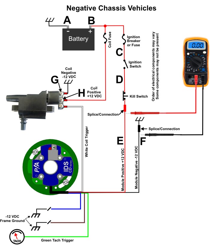 |
DRAWING 2 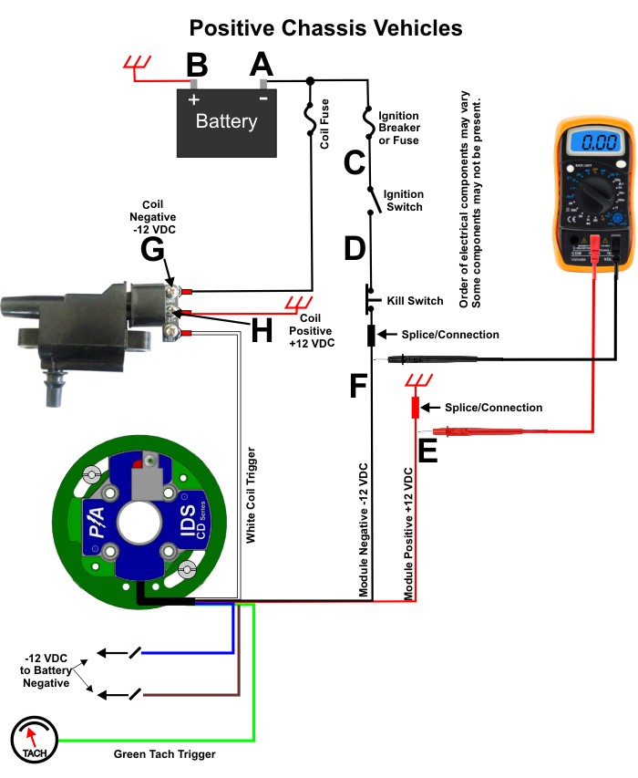 ● Check
Module Voltage- Connect the meter between module positive wire
(Point E) and module ground wire (Point F). The meter
connection should be after any splices/connectors in the module
power wires on the side of the wires towards the module. If the
vehicle has headlights turn the headlights on. Record the
module voltage then measure the battery voltage (Points A &
B). If there is more than a 1 volt difference between the
battery voltage and the module voltage there is excess voltage
drop in the wiring. The module voltage should not be below
12 volts with the engine running or 11 volts with the engine not
running.
● Check Coil Voltage- This test is
for coils with separate positive & negative supply wires
such as the MC-1 and MC-2 coils. Connect the meter between
coil positive screw (Point H) and coil ground screw (Point G).
Start the engine if the engine can be started. The ignition coil
will draw more current with the engine running. If the
vehicle has headlights turn the headlights on. Record the
coil voltage then measure the battery voltage (Points A &
B). If there is more than a 1 volt difference between the
battery voltage and the coil voltage there is excess voltage
drop in the wiring. The coil voltage should not be below 12
volts with the engine running or 11 volts with the engine not
running.
● Check Coil Voltage- This test is
for coils with with no negative power supply (coil type not
shown in drawing). Connect the meter between coil positive
(Point H) and ignition module ground wire (Point F). No
point G or negative supply will exist for these type of coils.
Start the engine if the engine can be started. The ignition coil
will draw more current with the engine running. If the
vehicle has headlights turn the headlights on. Record the coil
voltage then measure the battery voltage (Points A &
B). If there is more than a 1 volt difference between the
battery voltage and the coil voltage there is excess voltage
drop in the wiring. The coil voltage should not be below 12
volts with the engine running or 11 volts with the engine not
running.
● Check Voltage When Starting-
With a fully charged battery *, turn the engine over with the
meter connected to the battery posts (Points A & B). The
voltage should not go below 10 volts DC with the starter motor
running. If the voltage is lower check battery connections
and consider purchasing a new battery.
● Check charging system-
Measure the voltage at the battery posts (Points A & B)
while increasing the engine RPM to 4000-5000 RPM. If
the battery voltage at the battery posts is 15 Volts or higher
with the engine running you probably have a defective voltage
regulator. Repair or replace as necessary.
* WARNING: If using a battery
charger never attempt to start the engine or apply power to the
ignition with the charger attached. Remove charger before
starting. If the engine utilizes a starter motor and it
will not turn over after charging replace the battery or repair
starter motor, cables etc. Disconnect battery positive
cable before charging if it is suspected that the battery is
defective.
|
Voltage
Drop Test for Determining Which Component is Faulty (Do Voltage
Test First)
● Set volt meter to 20 Volt DC or
higher range
● For negative chassis vehicles
(refer to drawing 1) keep the negative meter wire on the battery
negative (Point A). Turn the ignition switch on. If
the vehicle has headlights turn the headlights on. While
observing the voltage move the positive meter probe from the
battery positive (Point B) to after the ignition
fuse/breaker (Point C) then to after the ignition switch (Point
D) then to after the kill switch (Point E) at the positive
connection of the ignition module. Take note of any
voltage drops. The voltage drops can also occur at any of the
connectors along the ignition system supply path. Each
installation is different the order of the components may vary
and some of these components may not exist. Any component or
connection between the battery and the ignition module or
ignition coil must be ruled out as each could cause a voltage
drop. Whenever the voltage drops more than a few tenths of a
volt you have a potentially faulty switch, connector or
wire. Jump the suspected bad component with wire and
operate the engine to verify that the defective component was
found.
● For positive chassis vehicles
(refer to drawing 2) keep the positive meter wire on the battery
negative (Point B). Turn the ignition switch on. If
the vehicle has headlights turn the headlights on. While
observing the voltage move the negative meter probe from the
battery negative (Point A) to after the ignition
fuse/breaker (Point C) then to after the ignition switch (Point
D) then to after the kill switch (Point F) at the negative
connection of the ignition module. Take note of any
voltage drops. The voltage drops can also occur at any of the
connectors along the ignition system supply path. Each
installation is different the order of the components may vary
and some of these components may not exist. Any component or
connection between the battery and the ignition module or
ignition coil must be ruled out as each could cause a voltage
drop. Whenever the voltage drops more than a few tenths of a
volt you have a potentially faulty switch, connector or
wire. Jump the suspected bad component with wire and
operate the engine to verify that the defective component was
found.
● For positive chassis vehicles
(refer to drawing 2) keep the positive meter wire on the battery
positive (Point B). Turn the ignition switch on. If
the vehicle has headlights turn the headlights on. While
observing the voltage move the negative meter probe from the
battery negative (Point A) then to after the ignition
fuse/breaker (Point C) then to after the ignition switch (Point
D) then to after kill switch (Point F) at the negative
connection of the ignition module. Take note of any
voltage drops. The voltage drops can also occur at any of the
connectors along the ignition system supply path. Each
installation is different the order of the components may vary
and some of these components may not exist. Everything between
the battery and the ignition module must be ruled out as each
could cause a voltage drop. Whenever the voltage drops more than
a few tenths of a volt you have a potentially faulty switch,
connector or wire. Jump the suspected bad component
with wire and operate the engine to verify that the defective
component was found.
|
Quick
Wiring Test (No Meter Required)*
● For negative chassis systems
jump a wire from the (+) of the battery to the ignition coil (+)
and to the ignition module (+). For positive chassis
systems jump a wire from the (-) of the battery to the ignition
coil (-) and to the ignition module (-). Do not hook power to
the ignition module coil trigger wire or you could damage the
module and void your warranty. Please refer to your owner's
manual for wiring details. Remember to disconnect the
jumper wires when finished with the test. The jumper wires
must be removed to stop the engine from running. Try
starting the engine to see if proper operation has been
restored.
● If the problem is remedied with
the above jumper wire test jump a wire across any of the
suspected components (ignition switch, kill switch, breakers) to
determine which component is causing the power loss. Check
heat shrunk connections closely (wires break at connector
crimp/solder joints). Visually inspect all wires looking
for melted or crimped wires. Run your hands along the
wires to find melted or bare wires. Tug on wires with
moderate pressure at connectors, fuses or switches to
verify they are securely attached.
● Replace the defective component
when located.
*Only perform jumper wire tests
long enough to determine if the power wiring is a problem
and remove the jumper when finished. Perform test in a
safe environment away from high traffic areas.
|
Charging
System Test
Regulator failures will usually present themselves by over-charging the battery. Sometimes headlight or taillight bulbs blow up from high voltage, or the battery gets hot. This can be diagnosed with a Digital MultiMeter (DMM). ● Connect your DMM (Digital
MultiMeter) to the battery terminals, red DMM lead to the
positive (+) terminal, black DMM lead to the negative (-)
terminal.
● Set the DMM to DC voltage mode,
20V range or higher.
● Start the engine.
● Note battery voltage at idle. It
should be in the range of 12V - 13.5 VDC at idle.
● Rev the engine to 4000-5000 RPM,
and check the DMM reading.
● The regulator should reach ~14.4
- 14.6VDC.
If the voltage continues increasing with RPM to 15VDC or higher, the regulation function is not operating correctly. The voltage regulator must be replaced. Regulator operation can be intermittent and may get progressively worse. |
High
Voltage Test and Plug Wire Test
● Remove spark plug.
Re-attach plug wire and place spark plug threaded area on frame
of engine. Turn over engine and observe spark gap of
plug. Do this for any cylinder suspected of not
having a spark.
● Set meter to measure resistance.
It should be placed in a range of at least 10K (10,000
Ohms). Measure the resistance of the spark plug
wires. The spark plug wires should be between 800 and
8,000 ohms. If the resistance is too low replace the wires with
the correct type or length of wires. If the resistance is
too high there is probably a break in the wires or a bad
connection or crimp. Inspect the wire boots and
connections making sure the center conductor of the wires is
touching the terminal. Some+times the insulation is
cracked and can short to the frame of an engine. Inspect
the plug wires for cracks, look for signs of arcing on the
frame, listen for crackling or snapping sounds. Observe the
engine in the dark while running for signs of high voltage leaks
in plug wires.
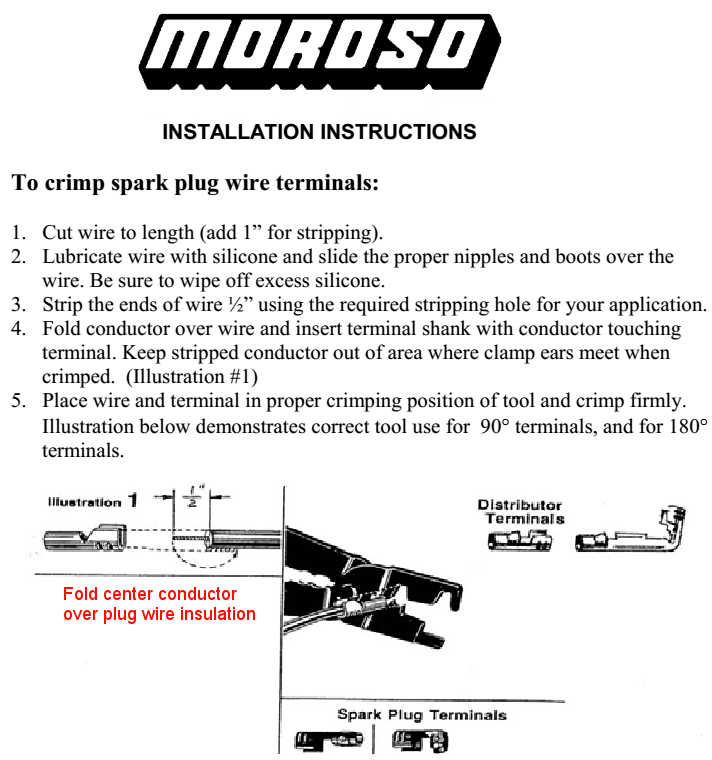
● The procedure for crimping spark
plug wires is shown below. Power Arc wires are typically 8
mm. Use the correct tool for the diameter of spark plug
wire used. Crimping tools are available at automotive
parts retailers, tool suppliers, larger department stores and
online.
 |
Coil Test (MC-1, MC-2 & Quad Pack
Coil Only)
● Remove the coil trigger wire
from the coil being tested. Remove the spark plug attached
to the coil your are testing. Re-attach the the spark plug wire
to the spark plug and lay the threaded portion of the spark plug
on the frame of engine. Apply power to the ignition
coil. The positive and negative terminals of the coil must
be connected to a power source. Attach a wire to the
trigger connection of the coil being tested and tap the wire to
the negative of the battery or the frame if a negative chassis
system is being used. You should be able to observe a
spark at the spark plug electrode if the coil is operating
properly. Remove the test wire from the trigger when
done.
|
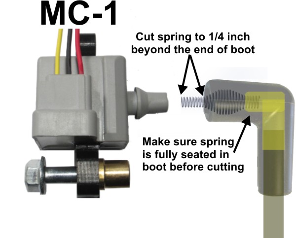
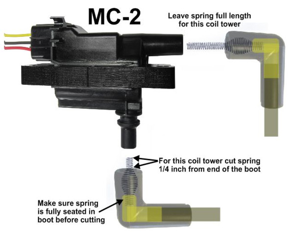
Ignition
coil spring lengths
● If the spring has not been cut
to the correct length, cut the spring to the lengths indicated
below for each coil type. Seat the spring in the coil wire
boot by applying pressure while rotating the spring.
  |
Cleaning
Aperture and Aligning Optical Sensor/Pickup
● Clean both apertures (slits) of
the optical sensor with alcohol using a fine bristle tooth
brush. Blow out the apertures with moderate air pressure
(approximately 60-80 psi).
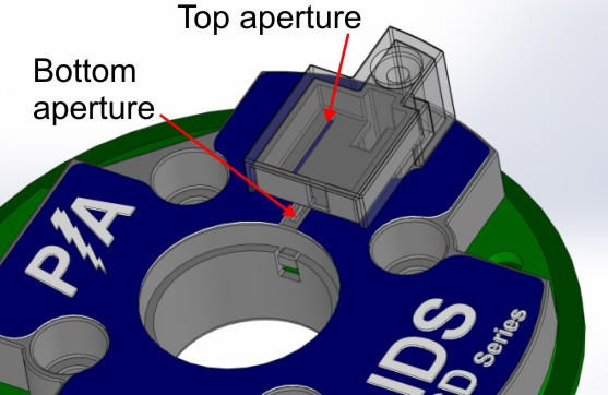 |
● Make sure the
encoder disk is in the zone highlighted in red below. The
encoder disk should be slightly below the mid-point of the optical
pickup/sensor
 You may click here to ask Power Arc a question concerning diagnosis of any ignition component problems not covered in the troubleshooting guide. |